Main Menu

pH Theory
Download this information for future reference
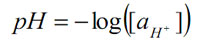
pH is a scale of active hydrogen ion concentration in aqueous solution. In pure water, the concentration of hydrogen ions is 10–7M. The pH scale converts this to a convenient positive number:
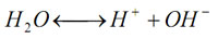
pH indicates acidity (pH<7), alkalinity (pH >7) or neutrality (pH = 7). Pure water undergoes autoprotolysis to yield equal numbers of hydrogen and hydroxide ions:
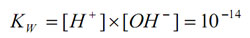
The equilibrium constant at 25oC is:
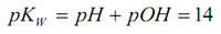
pOH is the negative logarithm of the active hydroxide concentration. The equilibrium expression can be rewritten as:
This equation applies for all aqueous systems. Very strong acids and bases can have pH’s <0 and >14 respectively. Although pH is defined for aqueous solutions, measurements can be made in non-aqueous solutions provided the solvent is sufficiently conductive, or a conductive solvent is added to a non-conductive sample.
Construction
A standard pH electrode consists of two electrochemical half-cells usually co-axially combined into a single housing called a “combination electrode” to form an electrical circuit. The sensing half-cell comprises a pH sensitive glass membrane attached to a sealed insulating tube containing a solution of fixed pH in contact with a silver-silver chloride element. A voltage proportional to pH is measured between the sensing half-cell and a reference half-cell which ideally maintains a stable potential independent of the sample. The following diagram represents the Intermediate Junction of Ionode's IJ Series.
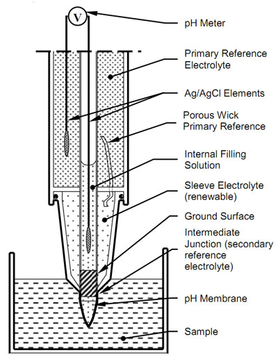
Figure 6
Part of the circuit is electronic (heavy lines) (see Figure 6). The remainder is ionic. Unlike other pH electrode measuring systems which rely on electron transfer such as antimony and quinhydrone, the pH glass electrode is insensitive to ORP.
pH glass is modified lithium silica which is a lithium ion conductor at room temperature. Hydrous glass ion exchange layers exist on both sides of the membrane (see Figure 7 - Figure 9). These allow reversible exchange between hydrogen and lithium ions.

Figure 7
Equal concentrations of H+ on either side of the membrane causes no potential to develop across the membrane (see Figure 7).

Figure 8
Unequal concentrations of H+on either side of the membrane cause the system to equalise the number of positive ions on either side of the membrane. This causes migration of a lithium ion through the membrane (see Figure 8).

Figure 9
As the negatively charged oxygen counter ions are fixed in the glass structure, a potential develops across the membrane (see Figure 9). This builds until the charge developed opposes further migration according to the Nernst equation.
The reference half-cell completes the circuit. The primary IJ reference is a silver/silver chloride element in a gelled saturated potassium chloride electrolyte. This makes solution contact with the secondary sleeve electrolyte through a low porosity wick. Usually, the sleeve electrolyte is concentrated potassium chloride. However, as the IJ reference has a double junction, it allows the use of other suitable sleeve electrolytes. Potassium chloride is the most commonly used reference electrolyte because of the similar size and mobility of the potassium and chloride ions. This minimizes charge separation when the sleeve electrolyte diffuses into the sample
Solution contact between the sleeve electrolyte and the sample is through the porous junction between the ground stem and the sleeve. This constriction allows uninhibited movement of ions between the sample and reference half cell to assure a repeatable reference junction potential. At the same time it does not grossly contaminate the sample with reference ions.

In common electrode designs, a porous restriction (typically a porous ceramic or fibre wick) is used to slow the flow (see Figure 10a).
If the restriction becomes clogged and movement of ions becomes inhibited, the electrode will appear to be stable in buffer solutions, but it may produce errors in non-ideal and low buffering capacity samples. The IJ reference system overcomes this by allowing free movement of ions past the restriction, allowing the junction to be cleaned and the sleeve electrolyte to be easily replaced. The result is a reference electrode system of assured reliability (see Figure 10b).
Output
The voltage output is related to the hydrogen ion activity by the Nernst equation:
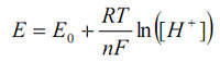
This can be rewritten in linear form by substituting in the definition of pH and grouping all the constants to give:
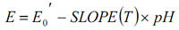
E0’ is referred to as the isopotential point. Theoretically, it is the pH which has no temperature dependence.
The IJ44 has been designed so that it is compatible with all modern pH meters.

Offset
Each pH electrode has a small offset which varies from electrode to electrode. It is due to an “asymmetry potential” across the membrane. It is usually within ±0.2pH for a new electrode, and requires correction by calibration in a buffer at or near pH 7. The offset increases as the electrode ages and is also an indication of the condition of the electrode, especially cleanliness. Most pH electrodes have pH0 value of close to pH 7.0.
Slope
The SLOPE is a function of temperature (T) and contains the conversion of the natural logarithm to the base ten logarithm. It is defined as the number of mV per unit of pH. It is manually or automatically (ATC) compensated in pH meters.
Table 1:Theoretical (Nernstian) Slope
|
T (oC) |
SLOPE(T) (mV) |
T (oC) |
SLOPE(T) (mV) |
|
0 |
54.197 |
30 |
60.149 |
|
5 |
55.189 |
35 |
61.141 |
|
10 |
56.181 |
38 |
61.737 |
|
15 |
57.173 |
40 |
62.133 |
|
20 |
58.165 |
45 |
63.126 |
|
25 |
59.157 |
50 |
64.118 |
A new electrode should have a slope between 95-102% of theoretical. Sub-Nernstian slope is corrected by calibration with a second buffer. As the pH membrane ages, the slope decreases. This affects the accuracy.
For best performance, the slope should be >95%. Some meters calculate and display % slope after calibration. It can also be accurately measured using the mV mode of a pH meter.
1) Measure the temperature of two buffers and select the pH values for the buffers at this temperature (see Table 2: pH Values of Standard Buffers at Various Temperatures)
2) Measure the mV readings for the two buffers. Allow several minutes for the electrode to attain thermal equilibrium with the buffers.
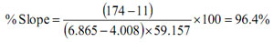
3) Divide the measured difference by the theoretical difference (see Table 1) and multiply by 100.
Example:
Buffer 1 (pH 6.865 @ 25ºC): +11 (mV)
Buffer 2 (pH 4.008 @ 25ºC): +174 (mV)
SLOPE(T=25ºC): 59.157 (mV/pH)
Note that ATC provided by pH meters only corrects the temperature term in the Nernst equation. It does not correct the temperature coefficients of buffers unless they are specified and the meter software calculates accordingly. With the exceptions of fully dissociated strong acids and bases, all samples have temperature coefficients as well. These vary depending on the nature of the sample and cannot be corrected by the pH meter. For best reporting, the temperature at which the measurement has been made should be stated.
Sodium Error
The selectivity of H+ over Na+ is extremely high, but small errors become apparent at high pH (i.e. low H+ concentration) and high Na+ concentration.
Corrections to the measurement can be made if the sodium concentration of the sample is known. The sodium error increases with aging.
A measured pH can be corrected by locating it on the x-axis and drawing a line straight up until it intersects the sodium concentration line of the sample (extrapolate between lines for sodium concentrations not drawn). Draw a line from the intersection directly over to the y-axis to determine the error in the measurement. The actual pH of the sample is determined by adding the error to the measured pH. For example, if a sample with 1M Na+ concentration measures pH 12.6, then the actual pH is 12.77.
The sodium error is larger in the “A” glass pH electrodes. As a consequence, “A” glass pH electrodes are best suited to pH measurements below pH12. The “A” glass would be preferred for measurements in strong acids, titrations and for measurement in lower conductivity samples.
A graph showing sodium error response for Ionodes' C Glass formulation is reproduced below.

Response Time
This varies according to the pH glass composition, membrane wall thickness, pH meter filtering, buffering capacity of the sample, measurement temperature (longest at <10C), lack of thermal equilibrium between the electrode and buffers/samples, cleanliness of the junction, and the age, chemical exposure history and cleanliness of the membrane. Most increases in response time for new electrodes are due to the latter.
Impedance
pH membranes typically have resistances of 100 – 1000 MOhm. This requires the pH meter to have an input impedance of at least 1012Ohms in order to avoid signal loss and polarisation of the electrode. The latter occurs when a significant current flows through the electrode. This alters the Ag/AgCl/sat KCl half cell potentials and permanently damages the membrane. Polarisation can be caused by damp or shorted connectors, poor connector insulation, a low impedance meter or meter circuit malfunction.